This tutorial covers rendering an introductory Hello Triangle program in Vulkan and C++.
A bare bones Vulkan set up can be simplified down into the steps:
- Create the window
- Create the Vulkan instance
- Enumerate the available GPUs
- Create the Vulkan device
- Create the graphics queue
- Initialize memory heaps/buffers
- Create the swapchain
- Create the render pass
- Create the framebuffers
Once that is set up, we can implement the actual rendering logic for Hello Triangle as follows:
- Create/upload the triangle vertex buffer
- Create the vertex/fragment shaders
- Create the graphics pipeline
- Implement the main loop and render function
The complete source code for this tutorial can be found in this github repository.
Before we start writing code, please make sure you have followed this tutorial to set up the required SDKs/libraries.
Once we have the required setup complete, we can start implementing our logic. We begin by including the required library headers and defining some required definitions/helper functions.
1.#include <cstdio>
2.#include <cstdarg>
3.#include <cstdint>
4.#include <functional>
6.#include <map>
7.#include <vector>
8.#include <SDL3/SDL.h>
10.#include <SDL3/SDL_vulkan.h>
11.#include <vulkan/vulkan.h>
13.enum
15.{
16. KB = 1024,
17. MB = 1024 * KB,
18. GB = 1024 * MB
19.};
20.const char* APP_NAME = "Hello Triangle";
22.enum
24.{
25. WIDTH = 1024,
26. HEIGHT = 1024
27.};
28.#define ALIGN(size, alignment) (((size) + ((alignment) - 1)) & ~((alignment) - 1))
30.enum : uint64_t { NANOSECONDS_PER_SECOND = 1000000000 };
32.void Assert(bool Condition, const char* ErrorMessage, ...)
34.{
35. if (!Condition)
36. {
37. std::va_list Args;
38. va_start(Args, ErrorMessage);
39. vprintf(ErrorMessage, Args);
41. putc('\n', stdout);
42. va_end(Args);
44. throw −1;
45. }
46.}
We will use the SDL library to create the window. SDL is a very popular/well supported cross platform library, and makes it very easy to create windows.
We start by initializing SDL and loading the Vulkan library, then we can create the SDL window.
1.SDL_Window* Window { nullptr };
2....
4.Assert(SDL_Init(SDL_INIT_VIDEO | SDL_INIT_AUDIO | SDL_INIT_EVENTS), "Could not initialize SDL");
6.Assert(SDL_Vulkan_LoadLibrary(nullptr), "Could not load the vulkan library");
7.SDL_PropertiesID WindowProperties = SDL_CreateProperties();
9.SDL_SetNumberProperty(WindowProperties, SDL_PROP_WINDOW_CREATE_X_NUMBER, SDL_WINDOWPOS_CENTERED);
10.SDL_SetNumberProperty(WindowProperties, SDL_PROP_WINDOW_CREATE_Y_NUMBER, SDL_WINDOWPOS_CENTERED);
11.SDL_SetNumberProperty(WindowProperties, SDL_PROP_WINDOW_CREATE_WIDTH_NUMBER, WIDTH);
12.SDL_SetNumberProperty(WindowProperties, SDL_PROP_WINDOW_CREATE_HEIGHT_NUMBER, HEIGHT);
13.SDL_SetStringProperty(WindowProperties, SDL_PROP_WINDOW_CREATE_TITLE_STRING, APP_NAME);
14.SDL_SetNumberProperty(WindowProperties, SDL_PROP_WINDOW_CREATE_VULKAN_BOOLEAN, true);
15.Window = SDL_CreateWindowWithProperties(WindowProperties);
17.SDL_DestroyProperties(WindowProperties);
19.Assert(Window != nullptr, "Could not create SDL window");
After the window is created, we need to poll and handle SDL's events. The main one being SDL_EVENT_QUIT, which tells the application
the user has pressed the close button. Here we also exit if the user presses the escape key.
1.bool Running { true };
2....
4.void Update(void)
6.{
7. SDL_Event event = { 0 };
8. while (SDL_PollEvent(&event) != 0)
9. {
10. switch (event.type)
11. {
12. case SDL_EVENT_QUIT:
13. {
14. Running = false; // The main loop will exit once this becomes false
15. break;
16. }
17. case SDL_EVENT_KEY_DOWN:
18. {
19. switch (event.key.scancode)
20. {
21. case SDL_SCANCODE_ESCAPE:
22. Running = false; // The main loop will exit once this becomes false
23. break;
24. default:
25. break;
26. }
27. break;
28. }
29. default:
30. break;
31. }
32. }
33.}
Before creating the Vulkan instance, the application can enumerate all the available layers/extensions available from the API/driver.
These layers/extensions can give optional functionality/features if the application requests them during instance creation.
We can enumerate the layers and extensions using the vkEnumerateDeviceLayerProperties and vkEnumerateDeviceExtensionProperties functions.
Normally an application will validate if its required layers/extensions are available, but here we simply print them out.
1.uint32_t ExtCount = 0;
2.uint32_t LayerCount = 0;
3.Assert(vkEnumerateInstanceLayerProperties(&LayerCount, nullptr) == VK_SUCCESS, "Could not get number of instance layers");
5.std::vector<VkLayerProperties> AvailableLayers(LayerCount);
7.Assert(vkEnumerateInstanceLayerProperties(&LayerCount, AvailableLayers.data()) == VK_SUCCESS, "Could not get instance layers");
8.for (uint32_t i = 0; i <= AvailableLayers.size(); i++)
10.{
11. const char* pLayerName = (i == 0) ? nullptr : AvailableLayers[i − 1].layerName;
12. Assert(vkEnumerateInstanceExtensionProperties(pLayerName, &ExtCount, nullptr) == VK_SUCCESS, "Could not get extension count for instance layer");
14. std::vector<VkExtensionProperties> AvailableExtensions(ExtCount);
16. Assert(vkEnumerateInstanceExtensionProperties(pLayerName, &ExtCount, AvailableExtensions.data()) == VK_SUCCESS, "Could not get extensions for instance layer");
17. printf("Instance layer: %s\n", (pLayerName == nullptr) ? "Global" : pLayerName);
19. for (uint32_t j = 0; j < AvailableExtensions.size(); j++)
20. {
21. printf("\t%s\n", AvailableExtensions[j].extensionName);
22. }
23.}
SDL requires certain extensions to be enabled when the Vulkan instance is created. We can get these using SDL_Vulkan_GetInstanceExtensions.
1.char const* const* RequiredSDLExtensions = SDL_Vulkan_GetInstanceExtensions(&ExtCount);
2.Assert(RequiredSDLExtensions != nullptr, "Could not get number of required SDL extensions");
3.std::vector<const char*> RequiredLayers;
5.std::vector<const char*> RequiredExtensions(RequiredSDLExtensions, RequiredSDLExtensions + ExtCount); // Create RequiredExtensions vector with copy of the RequiredSDLExtensions array
If you want to be thorough, you can validate these required extensions are supported by following the code in section A.
The validation layer can help catch bad parameters, memory leaks, invalid API calls, and many other errors. It is very useful for catching bugs. To enable it, simply add it to the required layer/extension list.
                                1.#ifdef DEBUG // Only add the validation layer/extension if this is a debug build
                                2.    RequiredLayers.push_back("VK_LAYER_KHRONOS_validation");
                                3.    RequiredExtensions.push_back(VK_EXT_DEBUG_REPORT_EXTENSION_NAME);
                                4.#endif
Note that enabling this validation extension is not enough, we need to do some additional set up after creating the instance. This will be covered in section 2.E.
To create the actual instance, we fill out the VkApplicationInfo and VkInstanceCreateInfo structures,
and call vkCreateInstance. The application structure specifies the app and engine names/versions, and the required Vulkan API version.
The instance structure will take a pointer to the application structure and the lists of the required layers/extensions.
1.VkInstance Instance { nullptr };
2....
4.VkApplicationInfo AppInfo =
6.{
7. .sType = VK_STRUCTURE_TYPE_APPLICATION_INFO,
8. .pNext = nullptr,
9. .pApplicationName = APP_NAME,
10. .applicationVersion = 1,
11. .pEngineName = APP_NAME,
12. .engineVersion = 1,
13. .apiVersion = VK_API_VERSION_1_0
14.};
15.VkInstanceCreateInfo InstanceInfo =
17.{
18. .sType = VK_STRUCTURE_TYPE_INSTANCE_CREATE_INFO,
19. .pNext = nullptr,
20. .flags = 0,
21. .pApplicationInfo = &AppInfo,
22. .enabledLayerCount = static_cast<uint32_t>(RequiredLayers.size()),
23. .ppEnabledLayerNames = RequiredLayers.data(),
24. .enabledExtensionCount = static_cast<uint32_t>(RequiredExtensions.size()),
25. .ppEnabledExtensionNames = RequiredExtensions.data()
26.};
27.Assert(vkCreateInstance(&InstanceInfo, nullptr, &Instance) == VK_SUCCESS, "Failed to create vulkan instance");
If you followed 2.C, once the instance is created, we need to set up the debug report callback which Vulkan
will use to send the debug messages. We first need to use
vkGetInstanceProcAddr to get the function pointers to the callbacks vkCreateDebugReportCallback and
vkDestroyDebugReportCallback. After getting the function addresses, we can create the debug report callback VulkanDebugReportCb and
object VkDebugReportCallbackEXT.
1.#ifdef DEBUG
2. VkDebugReportCallbackEXT hVkDebugReport { nullptr };
3. PFN_vkCreateDebugReportCallbackEXT vkCreateDebugReportCb { nullptr };
4. PFN_vkDestroyDebugReportCallbackEXT vkDestroyDebugReportCb { nullptr };
5.#endif
6....
8.#ifdef DEBUG
10. static VkBool32 VulkanDebugReportCb(VkDebugReportFlagsEXT flags, VkDebugReportObjectTypeEXT objectType, uint64_t object, size_t location, int32_t messageCode, const char* pLayerPrefix, const char* pMessage, void* pUserData)
11. {
12. printf("%s: %s\n", pLayerPrefix, pMessage);
13. return VK_FALSE; // The vulkan spec states the application should always return VK_FALSE, because VK_TRUE is only used in layer development
14. }
15.#endif
16....
18.#ifdef DEBUG
20. vkCreateDebugReportCb = reinterpret_cast<PFN_vkCreateDebugReportCallbackEXT>(vkGetInstanceProcAddr(Instance, "vkCreateDebugReportCallbackEXT"));
21. vkDestroyDebugReportCb = reinterpret_cast<PFN_vkDestroyDebugReportCallbackEXT>(vkGetInstanceProcAddr(Instance, "vkDestroyDebugReportCallbackEXT"));
22. Assert(vkCreateDebugReportCb != nullptr, "Could not get debug report callback");
24. Assert(vkDestroyDebugReportCb != nullptr, "Could not get debug report callback");
25. VkDebugReportCallbackCreateInfoEXT CallbackInfo =
27. {
28. .sType = VK_STRUCTURE_TYPE_DEBUG_REPORT_CALLBACK_CREATE_INFO_EXT,
29. .pNext = nullptr,
30. .flags = VK_DEBUG_REPORT_INFORMATION_BIT_EXT | VK_DEBUG_REPORT_WARNING_BIT_EXT | VK_DEBUG_REPORT_PERFORMANCE_WARNING_BIT_EXT |
31. VK_DEBUG_REPORT_ERROR_BIT_EXT | VK_DEBUG_REPORT_DEBUG_BIT_EXT,
32. .pfnCallback = VulkanDebugReportCb,
33. .pUserData = nullptr
34. };
35. Assert(vkCreateDebugReportCb(Instance, &CallbackInfo, nullptr, &hVkDebugReport) == VK_SUCCESS, "Failed to register debug callback\n");
37.#endif
Vulkan gives a list of all the GPUs in the current system through the vkEnumeratePhysicalDevices function.
1.uint32_t DeviceCount = 0;
2.Assert(vkEnumeratePhysicalDevices(Instance, &DeviceCount, nullptr) == VK_SUCCESS, "Could not get number of physical devices");
3.std::vector<VkPhysicalDevice> DeviceHandles(DeviceCount);
5.Assert(vkEnumeratePhysicalDevices(Instance, &DeviceCount, DeviceHandles.data()) == VK_SUCCESS, "Could not get physical devices");
Once we have all the device handles, we can get the properties of each device. This includes:
- The GPU name
- The GPU type (integrated, discrete, etc.)
- The types and counts of queues available on the GPU (graphics, compute, copy, etc.)
- The type and amounts of memory available in the GPU
We will be using a simple algorithm which selects the most preferred GPU based off the following criteria: GPU type (discrete vs integrated), the number of graphics queues available, and the amount of local memory available.
1.VkPhysicalDevice PhysicalDevice { nullptr };
2.uint32_t GraphicsQueueGroup { UINT32_MAX };
3....
5.// GPU type preference order - we are only interested in discrete and integrated adapters
7.const std::map<VkPhysicalDeviceType, uint32_t> PreferenceOrder =
8.{
9. { VK_PHYSICAL_DEVICE_TYPE_DISCRETE_GPU, 2 },
10. { VK_PHYSICAL_DEVICE_TYPE_INTEGRATED_GPU, 1 }
11.};
12.// Helper structure for comparing GPUs
14.struct PhysicalDeviceInfo
15.{
16. VkPhysicalDevice Handle = nullptr;
17. uint32_t OriginalIndex = 0;
18. uint32_t PreferenceIndex = 0;
19. uint32_t GraphicsQueueGroup = UINT32_MAX;
20. uint32_t NumGraphicsQueues = 0;
21. uint64_t LocalHeapSize = 0;
22. // Boolean operator to check if a device is valid
24. operator bool() const
25. {
26. return (Handle != nullptr)
27. && (PreferenceIndex > 0)
28. && (GraphicsQueueGroup != UINT32_MAX);
29. }
30. // Comparison operator to compare two devices
32. // Checks if this device has a greater preference, graphics queue count, and local heap size than the other device
33. bool operator > (const PhysicalDeviceInfo& rOtherDevice) const
34. {
35. return std::tie(this−>PreferenceIndex, this−>NumGraphicsQueues, this−>LocalHeapSize) >
36. std::tie(rOtherDevice.PreferenceIndex, rOtherDevice.NumGraphicsQueues, rOtherDevice.LocalHeapSize);
37. }
38.};
39.PhysicalDeviceInfo SelectedDevice = {};
41.for (uint32_t i = 0; i < DeviceHandles.size(); i++)
43.{
44. PhysicalDeviceInfo DeviceInfo = { DeviceHandles[i], i };
45. VkPhysicalDeviceProperties DeviceProperties {};
47. VkPhysicalDeviceMemoryProperties MemoryProperties {};
48. vkGetPhysicalDeviceProperties(DeviceHandles[i], &DeviceProperties);
50. vkGetPhysicalDeviceMemoryProperties(DeviceHandles[i], &MemoryProperties);
51. uint32_t QueueCount = 0;
53. vkGetPhysicalDeviceQueueFamilyProperties(DeviceHandles[i], &QueueCount, nullptr);
54. std::vector<VkQueueFamilyProperties> QueueGroups(QueueCount);
56. vkGetPhysicalDeviceQueueFamilyProperties(DeviceHandles[i], &QueueCount, QueueGroups.data());
57. std::map<VkPhysicalDeviceType, uint32_t>::const_iterator it = PreferenceOrder.find(DeviceProperties.deviceType);
59. if (it != PreferenceOrder.end())
60. {
61. DeviceInfo.PreferenceIndex = it−>second;
62. }
63. for (uint32_t j = 0; j < QueueGroups.size(); j++)
65. {
66. if (QueueGroups[j].queueFlags & VK_QUEUE_GRAPHICS_BIT)
67. {
68. DeviceInfo.GraphicsQueueGroup = std::min(DeviceInfo.GraphicsQueueGroup, j); // Pick the first (minimum) available group, we only use 1 gfx queue, so the group does not matter
69. DeviceInfo.NumGraphicsQueues += QueueGroups[j].queueCount;
70. }
71. }
72. for (uint32_t j = 0; j < MemoryProperties.memoryHeapCount; j++)
74. {
75. if (MemoryProperties.memoryHeaps[j].flags & VK_MEMORY_HEAP_DEVICE_LOCAL_BIT)
76. {
77. DeviceInfo.LocalHeapSize += MemoryProperties.memoryHeaps[j].size;
78. }
79. }
80. if (DeviceInfo)
82. {
83. SelectedDevice = (DeviceInfo > SelectedDevice) ? DeviceInfo : SelectedDevice;
84. }
85.}
86.Assert(SelectedDevice, "Could not find a supported GPU");
88.PhysicalDevice = SelectedDevice.Handle;
90.GraphicsQueueGroup = SelectedDevice.GraphicsQueueGroup;
Note we also store the graphics queue group index because this will be used to create the graphics queue later on.
Once the physical device is determined, we have to create the logical device.
Similar to when we had created the instance, we can get the device's available layers/extensions using the functions vkEnumerateDeviceLayerProperties and vkEnumerateDeviceExtensionProperties.
1.uint32_t ExtCount = 0;
2.uint32_t LayerCount = 0;
3.Assert(vkEnumerateDeviceLayerProperties(PhysicalDevice, &LayerCount, nullptr) == VK_SUCCESS, "Failed to get number of device layers");
5.std::vector<VkLayerProperties> AvailableLayers(LayerCount);
7.Assert(vkEnumerateDeviceLayerProperties(PhysicalDevice, &LayerCount, AvailableLayers.data()) == VK_SUCCESS, "Failed to get device layers");
8.for (uint32_t i = 0; i <= AvailableLayers.size(); i++)
10.{
11. const char* pLayerName = (i == 0) ? nullptr : AvailableLayers[i − 1].layerName;
12. Assert(vkEnumerateDeviceExtensionProperties(PhysicalDevice, pLayerName, &ExtCount, nullptr) == VK_SUCCESS, "Could not get extension count for instance layer");
14. std::vector<VkExtensionProperties> AvailableExtensions(ExtCount);
16. Assert(vkEnumerateDeviceExtensionProperties(PhysicalDevice, pLayerName, &ExtCount, AvailableExtensions.data()) == VK_SUCCESS, "Could not get extensions for instance layer");
17. printf("Device layer: %s\n", (pLayerName == nullptr) ? "Global" : pLayerName);
19. for (uint32_t j = 0; j < AvailableExtensions.size(); j++)
20. {
21. printf("\t%s\n", AvailableExtensions[j].extensionName);
22. }
23.}
Note that we require the VK_KHR_SWAPCHAIN_EXTENSION_NAME extension when creating the logical device, because we will be creating a swapchain on this device.
Once we have figured out which layers/extensions are available and which ones we need, we can create the device. Note that we also have to request the queues we will be using
at the device creation time in the VkDeviceQueueCreateInfo structure. Here we only request the one graphics queue from the group we picked in section 3.
1.VkDevice Device { nullptr };
2....
4.std::vector<const char*> RequiredExtensions { VK_KHR_SWAPCHAIN_EXTENSION_NAME };
6.const float QueuePriority = 1.0f;
8.VkDeviceQueueCreateInfo QueueInfo =
10.{
11. .sType = VK_STRUCTURE_TYPE_DEVICE_QUEUE_CREATE_INFO,
12. .pNext = nullptr,
13. .flags = 0,
14. .queueFamilyIndex = GraphicsQueueGroup,
15. .queueCount = 1,
16. .pQueuePriorities = &QueuePriority
17.};
18.VkDeviceCreateInfo DeviceInfo =
20.{
21. .sType = VK_STRUCTURE_TYPE_DEVICE_CREATE_INFO,
22. .pNext = nullptr,
23. .flags = 0,
24. .queueCreateInfoCount = 1,
25. .pQueueCreateInfos = &QueueInfo,
26. .enabledLayerCount = 0,
27. .ppEnabledLayerNames = nullptr,
28. .enabledExtensionCount = static_cast<uint32_t>(RequiredExtensions.size()),
29. .ppEnabledExtensionNames = RequiredExtensions.data(),
30. .pEnabledFeatures = nullptr
31.};
32.Assert(vkCreateDevice(PhysicalDevice, &DeviceInfo, nullptr, &Device) == VK_SUCCESS, "Could not create vk device");
We already created the graphics queue in section 4, so we can simply get a handle to it using vkGetDeviceQueue.
1.VkQueue GraphicsQueue { nullptr };
2....
4.vkGetDeviceQueue(Device, GraphicsQueueGroup, 0, &GraphicsQueue);
6.Assert(GraphicsQueue != nullptr, "Could not get gfx queue 0");
However, the queue still needs a couple more objects for us to be able to use it. Those objects are:
- A command pool
- A command buffer
- A fence
A command pool, represented by the structure VkCommandPool, is used to allocate command buffers. Command buffers, represented by the structure
VkCommandBuffer, are used to record commands (i.e. rendering/compute/copy commands, etc.). A command pool can be used to allocate many command buffers,
but we will only need one for our simple app. And lastly, the fence is used for syncronizing work between the CPU and GPU. We will give this fence object
to the graphics queue when we submit work to it, and this fence will get signalled once the workload finishes. This will let us synchronize the CPU by waiting on the fence for the GPU submission to finish.
1.VkCommandPool CommandPool { nullptr };
2.VkCommandBuffer CommandBuffer { nullptr };
3.VkFence Fence { nullptr };
4....
6.VkCommandPoolCreateInfo CommandPoolInfo =
8.{
9. .sType = VK_STRUCTURE_TYPE_COMMAND_POOL_CREATE_INFO,
10. .pNext = nullptr,
11. .flags = VK_COMMAND_POOL_CREATE_TRANSIENT_BIT | VK_COMMAND_POOL_CREATE_RESET_COMMAND_BUFFER_BIT,
12. .queueFamilyIndex = GraphicsQueueGroup
13.};
14.Assert(vkCreateCommandPool(Device, &CommandPoolInfo, nullptr, &CommandPool) == VK_SUCCESS, "Could not create the command pool");
16.VkCommandBufferAllocateInfo CommandBufferInfo =
18.{
19. .sType = VK_STRUCTURE_TYPE_COMMAND_BUFFER_ALLOCATE_INFO,
20. .pNext = nullptr,
21. .commandPool = CommandPool,
22. .level = VK_COMMAND_BUFFER_LEVEL_PRIMARY,
23. .commandBufferCount = 1
24.};
25.Assert(vkAllocateCommandBuffers(Device, &CommandBufferInfo, &CommandBuffer) == VK_SUCCESS, "Could not create the command buffer");
27.VkFenceCreateInfo FenceInfo =
29.{
30. .sType = VK_STRUCTURE_TYPE_FENCE_CREATE_INFO,
31. .pNext = nullptr,
32. .flags = 0
33.};
34.Assert(vkCreateFence(Device, &FenceInfo, nullptr, &Fence) == VK_SUCCESS, "Failed to create fence");
Memory management is a very important concept in Vulkan. The developer is responsible for figuring out which parts of the memory to use, how to manage the memory usage, etc. In this program, we are only concerned with two categories of memory:
- Device local memory (GPU VRAM) vs. system memory (System RAM)
- Host visible memory (memory visible to the CPU)
Discrete GPUs usually have their own onboard local video memory (VRAM) which is optimal for GPU access. Integrated GPUs usually use the system RAM and do not have dedicated VRAM like discrete GPUs.
On older systems/discrete GPUs, only a small portion (usually 256 MB) of the GPU VRAM is visible (readable/writable) by the CPU. Modern systems/discrete GPUs have resizable bar, which makes the entire GPU VRAM visible to the CPU.
The GPU is able to access system RAM, but it not as fast as its own local VRAM. There are scenarios where the system RAM is needed. It is up to the developer to determine what type of memory is most appropriate for their purpose. This makes vulkan as powerful as it is, giving the developer a lot of control and optimization oppurtunity.
If resizable bar is enabled, our memory management logic is very simple as we can copy our data directly to the GPU's VRAM.
However, if resizable is not enabled, we need to have two heaps. Our primary heap will be on the GPU's VRAM as that is the most optimal for GPU access. We will have a secondary upload heap on the system RAM which will act as a staging area. Data will be copied to the upload heap (system RAM) first, and then a copy command will be submitted to the GPU to copy the contents from the upload heap to its primary heap (local VRAM).
We begin by getting the device's memory properties, using vkGetPhysicalDeviceMemoryProperties. This will populate the VkPhysicalDeviceMemoryProperties structure,
giving us information on all the memory heaps and types available for the device we selected. From there we will figure out the most optimal heaps for our application, as described above. Note that our
logic uses coherent memory wherever it can - this is because coherent memory is more optimal as sequential CPU writes will be write combined, making them much faster. Also note that a benefit of coherent memory types is that
we don't need to flush our writes using vkFlushMappedMemoryRanges; however we still do this in this program to keep the code simpler. In actual programs, it will be more optimal to skip the vkFlushMappedMemoryRanges
when coherent memory types are being used.
1.uint32_t PrimaryHeap { UINT32_MAX };
2.uint32_t UploadHeap { UINT32_MAX };
3.VkPhysicalDeviceMemoryProperties MemoryProperties {};
5....
7.vkGetPhysicalDeviceMemoryProperties(PhysicalDevice, &MemoryProperties);
9.// Helper lambda to scan available memory types
11.std::function<bool(uint32_t, uint32_t&)> FindHeap = [&](uint32_t Flags, uint32_t& MemoryType) −> bool
12.{
13. uint32_t Mask = VK_MEMORY_PROPERTY_DEVICE_LOCAL_BIT | VK_MEMORY_PROPERTY_HOST_VISIBLE_BIT | VK_MEMORY_PROPERTY_HOST_COHERENT_BIT;
14. uint64_t MaxSize = 0;
15. MemoryType = UINT32_MAX;
16. for (uint32_t i = 0; i < MemoryProperties.memoryTypeCount; i++)
17. {
18. uint32_t HeapIndex = MemoryProperties.memoryTypes[i].heapIndex;
19. uint64_t HeapSize = MemoryProperties.memoryHeaps[HeapIndex].size;
20. uint32_t HeapFlags = MemoryProperties.memoryTypes[i].propertyFlags;
21. if ((HeapFlags & Mask) == Flags && HeapSize > MaxSize)
22. {
23. MemoryType = i;
24. MaxSize = HeapSize;
25. }
26. }
27. return (MemoryType != UINT32_MAX);
28.};
29.uint32_t GpuLocalCpuVisibleHeap = UINT32_MAX; // GPU Local VRAM + CPU Visible Heap
31.uint32_t GpuLocalCpuInvisibleHeap = UINT32_MAX; // GPU Local VRAM + CPU Invisible Heap
32.// Try to find GpuLocalCpuVisibleHeap
34.if (FindHeap(VK_MEMORY_PROPERTY_DEVICE_LOCAL_BIT | VK_MEMORY_PROPERTY_HOST_VISIBLE_BIT | VK_MEMORY_PROPERTY_HOST_COHERENT_BIT, GpuLocalCpuVisibleHeap)) {} // GPU Local VRAM, HostVisible, HostCoherent, !HostCached
35.else if (FindHeap(VK_MEMORY_PROPERTY_DEVICE_LOCAL_BIT | VK_MEMORY_PROPERTY_HOST_VISIBLE_BIT, GpuLocalCpuVisibleHeap)) {} // GPU Local VRAM, HostVisible, !HostCoherent, !HostCached
36.// Try to find GpuLocalCpuInvisibleHeap
38.if (FindHeap(VK_MEMORY_PROPERTY_DEVICE_LOCAL_BIT, GpuLocalCpuInvisibleHeap)) {} // GPU Local VRAM, !HostVisible, !HostCoherent, !HostCached
39.if (GpuLocalCpuVisibleHeap != UINT32_MAX && GpuLocalCpuInvisibleHeap != UINT32_MAX
41. && MemoryProperties.memoryTypes[GpuLocalCpuVisibleHeap].heapIndex == MemoryProperties.memoryTypes[GpuLocalCpuInvisibleHeap].heapIndex)
42.{
43. // If both the GPU Local VRAM + CPU visible and CPU invisible memory types are on the same memory heap, we can just use the CPU visible one
44. // This happens when resizable bar is enabled
45. PrimaryHeap = GpuLocalCpuVisibleHeap;
46. UploadHeap = UINT32_MAX; // Upload heap is not needed, we will write our data directly to the GPU VRAM
47.}
48.else if (GpuLocalCpuVisibleHeap != UINT32_MAX && GpuLocalCpuInvisibleHeap == UINT32_MAX)
49.{
50. // If there is no GPU Local VRAM + CPU invisible heap, but there is a GPU Local VRAM + CPU visible heap, we can use that
51. // This can happen on iGPUs
52. PrimaryHeap = GpuLocalCpuVisibleHeap;
53. UploadHeap = UINT32_MAX; // Upload heap is not needed, we will write our data directly to the GPU VRAM
54.}
55.else if (GpuLocalCpuInvisibleHeap != UINT32_MAX)
56.{
57. // Otherwise we try to default to the primary heap being the GPU Local VRAM + CPU invisible heap
58. // And the upload heap being on the system memory
59. PrimaryHeap = GpuLocalCpuInvisibleHeap;
60. if (FindHeap(VK_MEMORY_PROPERTY_HOST_VISIBLE_BIT | VK_MEMORY_PROPERTY_HOST_COHERENT_BIT, UploadHeap)) {}
62. else if (FindHeap(VK_MEMORY_PROPERTY_HOST_VISIBLE_BIT, UploadHeap)) {}
63. else
64. {
65. // Cannot find a suitable upload heap
66. PrimaryHeap = UINT32_MAX;
67. UploadHeap = UINT32_MAX;
68. }
69.}
70.if (PrimaryHeap == UINT32_MAX)
72.{
73. // If we couldn't find suitable device local memory, we fall back to system memory for the primary heap
74. if (FindHeap(VK_MEMORY_PROPERTY_HOST_VISIBLE_BIT | VK_MEMORY_PROPERTY_HOST_COHERENT_BIT, PrimaryHeap)) {}
75. else if (FindHeap(VK_MEMORY_PROPERTY_HOST_VISIBLE_BIT, PrimaryHeap)) {}
76. else
77. {
78. Assert(false, "Unable to find primary heap");
79. }
80.}
If we are using an upload heap we need to allocate a large buffer in that heap. This buffer will be used as the intermediate staging buffer for data before
it gets transferred to the primary heap for future resources. Note that after we create the upload buffer, we also have to map it to the CPU address space using vkMapMemory, so that the
CPU can access it.
1.VkBuffer UploadBuffer { nullptr };
2.VkDeviceMemory UploadBufferMemory { nullptr };
3.uint64_t UploadBufferSize { 0 };
5.void* UploadBufferCpuVA { nullptr };
6....
8.// If we have an upload heap, we will need an upload buffer on that heap
10.if (UploadHeap != UINT32_MAX)
11.{
12. uint64_t HeapSize = MemoryProperties.memoryHeaps[MemoryProperties.memoryTypes[UploadHeap].heapIndex].size;
13. UploadBufferSize = std::min(ALIGN(HeapSize / 4, MB), static_cast<uint64_t>(16 * MB));
14. VkBufferCreateInfo UploadBufferInfo =
16. {
17. .sType = VK_STRUCTURE_TYPE_BUFFER_CREATE_INFO,
18. .pNext = nullptr,
19. .flags = 0,
20. .size = UploadBufferSize,
21. .usage = VK_BUFFER_USAGE_TRANSFER_SRC_BIT,
22. .sharingMode = VK_SHARING_MODE_EXCLUSIVE,
23. .queueFamilyIndexCount = 0,
24. .pQueueFamilyIndices = nullptr
25. };
26. Assert(vkCreateBuffer(Device, &UploadBufferInfo, nullptr, &UploadBuffer) == VK_SUCCESS, "Failed to create upload buffer");
28. VkMemoryRequirements UploadBufferRequirements = {};
30. AllocateMemory(UploadBuffer, UploadHeap, UploadBufferRequirements, UploadBufferMemory);
31. Assert(vkBindBufferMemory(Device, UploadBuffer, UploadBufferMemory, 0) == VK_SUCCESS, "Failed to bind upload buffer memory");
33. Assert(vkMapMemory(Device, UploadBufferMemory, 0, UploadBufferRequirements.size, 0, &UploadBufferCpuVA) == VK_SUCCESS, "Failed to map upload buffer memory");
34.}
This is the helper function used above, which allocates memory directly from a heap given its index. This will be useful for other allocations as well, such as the vertex buffer, and any other future allocations we need.
1.void AllocateMemory(VkBuffer hBuffer, uint32_t HeapIndex, VkMemoryRequirements& rMemoryRequirements, VkDeviceMemory& rMemory) const
2.{
3. vkGetBufferMemoryRequirements(Device, hBuffer, &rMemoryRequirements);
4. if ((rMemoryRequirements.memoryTypeBits & (1 << HeapIndex)) == 0)
6. {
7. Assert(false, "Required memory heap not supported for allocation");
8. }
9. VkMemoryAllocateInfo AllocationInfo =
11. {
12. .sType = VK_STRUCTURE_TYPE_MEMORY_ALLOCATE_INFO,
13. .pNext = nullptr,
14. .allocationSize = rMemoryRequirements.size,
15. .memoryTypeIndex = HeapIndex
16. };
17. Assert(vkAllocateMemory(Device, &AllocationInfo, nullptr, &rMemory) == VK_SUCCESS, "Failed to allocate memory");
19.}
The swapchain contains the sequence of images which we will render to and present on the screen.
Before we create the swapchain, we need to create a Vulkan surface for our SDL window. This surface will allow Vulkan to render on SDL's window,
and will be required for creating the swapchain. SDL provides a function SDL_Vulkan_CreateSurface to create this surface.
1.VkSurfaceKHR Surface { nullptr };
2....
4.Assert(SDL_Vulkan_CreateSurface(Window, Instance, nullptr, &Surface), "Failed to create surface");
After we create the surface, we need to check if our required surface formats and presentation mode are supported. The surface format
is the format of the swapchain images - in our case VK_FORMAT_B8G8R8A8_UNORM, which gives 8 bits to each red/green/blue/alpha component.
The presentation mode controls how the images of the swapchain are presented. We will be using VK_PRESENT_MODE_FIFO_KHR, which will present the swapchain images one by one in a queue
and will only present an image once the previous one has been fully presented (i.e. vertically synced).
1.VkSurfaceFormatKHR SurfaceFormat { VK_FORMAT_UNDEFINED };
2....
4.uint32_t PresentModeCount = 0;
6.uint32_t SurfaceFormatCount = 0;
7.Assert(vkGetPhysicalDeviceSurfacePresentModesKHR(PhysicalDevice, Surface, &PresentModeCount, nullptr) == VK_SUCCESS, "Could not get the number of supported presentation modes");
9.Assert(vkGetPhysicalDeviceSurfaceFormatsKHR(PhysicalDevice, Surface, &SurfaceFormatCount, nullptr) == VK_SUCCESS, "Could not get the number of supported surface formats");
10.std::vector<VkPresentModeKHR> PresentModes(PresentModeCount);
12.std::vector<VkSurfaceFormatKHR> SurfaceFormats(SurfaceFormatCount);
13.Assert(vkGetPhysicalDeviceSurfacePresentModesKHR(PhysicalDevice, Surface, &PresentModeCount, PresentModes.data()) == VK_SUCCESS, "Could not get the supported presentation modes");
15.Assert(vkGetPhysicalDeviceSurfaceFormatsKHR(PhysicalDevice, Surface, &SurfaceFormatCount, SurfaceFormats.data()) == VK_SUCCESS, "Could not get the number of supported surface formats");
16.for (std::vector<VkSurfaceFormatKHR>::const_iterator it = SurfaceFormats.begin(); it != SurfaceFormats.end(); it++)
18.{
19. if (it−>format == VK_FORMAT_B8G8R8A8_UNORM) { SurfaceFormat = *it; break; }
20.}
21.Assert(SurfaceFormat.format != VK_FORMAT_UNDEFINED, "Could not find required surface format");
23.Assert(std::find(PresentModes.begin(), PresentModes.end(), VK_PRESENT_MODE_FIFO_KHR) != PresentModes.end(), "Could not find required present mode");
We also need to tell the swapchain the size of the images to use and the minimum numbers of swapchain images to create. For that information we first call vkGetPhysicalDeviceSurfaceCapabilitiesKHR
to get the surface capabilities, which will tell us the current surface's dimensions in the currentExtent field, and the minimum number of images required in the minImageCount field.
Once we have this information, we can create the swapchain.
1.VkSwapchainKHR Swapchain { nullptr };
2....
4.VkSurfaceCapabilitiesKHR SurfaceCapabilities = { 0 };
6.Assert(vkGetPhysicalDeviceSurfaceCapabilitiesKHR(PhysicalDevice, Surface, &SurfaceCapabilities) == VK_SUCCESS, "Could not get surface capabilities");
7.VkSwapchainCreateInfoKHR SwapchainInfo =
9.{
10. .sType = VK_STRUCTURE_TYPE_SWAPCHAIN_CREATE_INFO_KHR,
11. .pNext = nullptr,
12. .flags = 0,
13. .surface = Surface,
14. .minImageCount = SurfaceCapabilities.minImageCount,
15. .imageFormat = SurfaceFormat.format,
16. .imageColorSpace = SurfaceFormat.colorSpace,
17. .imageExtent =
18. {
19. .width = SurfaceCapabilities.currentExtent.width,
20. .height = SurfaceCapabilities.currentExtent.height
21. },
22. .imageArrayLayers = 1,
23. .imageUsage = VK_IMAGE_USAGE_COLOR_ATTACHMENT_BIT,
24. .imageSharingMode = VK_SHARING_MODE_EXCLUSIVE,
25. .queueFamilyIndexCount = 0,
26. .pQueueFamilyIndices = nullptr,
27. .preTransform = VK_SURFACE_TRANSFORM_IDENTITY_BIT_KHR,
28. .compositeAlpha = VK_COMPOSITE_ALPHA_OPAQUE_BIT_KHR,
29. .presentMode = VK_PRESENT_MODE_FIFO_KHR,
30. .clipped = VK_TRUE,
31. .oldSwapchain = nullptr
32.};
33.Assert(vkCreateSwapchainKHR(Device, &SwapchainInfo, nullptr, &Swapchain) == VK_SUCCESS, "Failed to create swapchain");
After we create the swapchain, we can get the swapchain's images using vkGetSwapchainImagesKHR. This will be
useful for section 9 when we create the framebuffers.
1.enum
2.{
3. MinSwapchainImages = 2,
4. MaxSwapchainImages = 4
5.};
6.uint32_t NumSwapchainImages { 0 };
8.VkImage SwapchainImages[MaxSwapchainImages] {};
10....
12.Assert(vkGetSwapchainImagesKHR(Device, Swapchain, &NumSwapchainImages, nullptr) == VK_SUCCESS, "Could not get number of swapchain images");
14.Assert((NumSwapchainImages >= MinSwapchainImages) && (NumSwapchainImages <= MaxSwapchainImages), "Invalid number of swapchain images");
15.Assert(vkGetSwapchainImagesKHR(Device, Swapchain, &NumSwapchainImages, SwapchainImages) == VK_SUCCESS, "Could not get swapchain images");
Lastly, we need to create semaphores to syncronize access to the swapchain's images. We will need two sets of them for section 13 - one set for waiting for access to the swapchain's image before rendering, and one set for waiting for the swapchain's image to become ready to be presented after rendering is finished.
1.VkSemaphore RenderSemaphores[MaxSwapchainImages] {};
2.VkSemaphore PresentSemaphores[MaxSwapchainImages] {};
3....
5.VkSemaphoreCreateInfo SemaphoreInfo =
7.{
8. .sType = VK_STRUCTURE_TYPE_SEMAPHORE_CREATE_INFO,
9. .pNext = nullptr,
10. .flags = 0
11.};
12.for (uint32_t i = 0; i < NumSwapchainImages; i++)
14.{
15. Assert(vkCreateSemaphore(Device, &SemaphoreInfo, nullptr, &RenderSemaphores[i]) == VK_SUCCESS, "Failed to create render semaphore %u", i);
16. Assert(vkCreateSemaphore(Device, &SemaphoreInfo, nullptr, &PresentSemaphores[i]) == VK_SUCCESS, "Failed to create present semaphore %u", i);
17.}
The render pass is used to describe the render targets/attachments the current rendering workload will use. This object will be is necessary to create the framebuffer, and also required by Vulkan in the main rendering logic since rendering operations can only be done in render passes. In this example, we will only be rendering to the swapchain surfaces.
We begin by describing the attachment format, the color/depth/stencil buffer content load/store behaviours, and image layout at the beginning and end of the render pass.
This information is specified an array of VkAttachmentDescription structures,
and one is needed for each attachment the render pass will use. In our case, we will only have one color attachment, which will be the swapchain surface.
                                 1.VkAttachmentDescription AttachmentDescriptions[] =
                                 2.{
                                 3.    { // Color attachment
                                 4.        .flags = 0,
                                 5.        .format = SurfaceFormat.format,
                                 6.        .samples = VK_SAMPLE_COUNT_1_BIT,
                                 7.        .loadOp = VK_ATTACHMENT_LOAD_OP_CLEAR,
                                 8.        .storeOp = VK_ATTACHMENT_STORE_OP_STORE,
                                 9.        .stencilLoadOp = VK_ATTACHMENT_LOAD_OP_DONT_CARE,
                                10.        .stencilStoreOp = VK_ATTACHMENT_STORE_OP_DONT_CARE,
                                11.        .initialLayout = VK_IMAGE_LAYOUT_UNDEFINED, // image layout undefined at the beginning of the render pass
                                12.        .finalLayout = VK_IMAGE_LAYOUT_PRESENT_SRC_KHR // prepare the color attachment for presentation
                                13.    }
                                14.};
After describing the attachments, we must describe the subpasses. The subpass will list and index the attachments defined in the render pass by their index and define the corresponding layouts during the subpass. We will only have one pass, so we only define one VkSubpassDescription.
1.VkAttachmentReference ColorAttachments[] =
2.{
3. { // Color attachment
4. .attachment = 0,
5. .layout = VK_IMAGE_LAYOUT_COLOR_ATTACHMENT_OPTIMAL // image layout is VK_IMAGE_LAYOUT_COLOR_ATTACHMENT_OPTIMAL during render pass
6. }
7.};
8.VkSubpassDescription SubpassDescription =
10.{
11. .flags = 0,
12. .pipelineBindPoint = VK_PIPELINE_BIND_POINT_GRAPHICS,
13. .inputAttachmentCount = 0,
14. .pInputAttachments = nullptr,
15. .colorAttachmentCount = 1,
16. .pColorAttachments = ColorAttachments,
17. .pResolveAttachments = nullptr,
18. .pDepthStencilAttachment = nullptr,
19. .preserveAttachmentCount = 0,
20. .pPreserveAttachments = nullptr
21.};
Once these objects are prepared, the render pass can be created.
1.VkRenderPass RenderPass { nullptr };
2....
4.VkRenderPassCreateInfo RenderPassInfo =
6.{
7. .sType = VK_STRUCTURE_TYPE_RENDER_PASS_CREATE_INFO,
8. .pNext = nullptr,
9. .flags = 0,
10. .attachmentCount = sizeof(AttachmentDescriptions) / sizeof(VkAttachmentDescription),
11. .pAttachments = AttachmentDescriptions,
12. .subpassCount = 1,
13. .pSubpasses = &SubpassDescription,
14. .dependencyCount = 0,
15. .pDependencies = nullptr
16.};
17.Assert(vkCreateRenderPass(Device, &RenderPassInfo, nullptr, &RenderPass) == VK_SUCCESS, "Failed to create render pass");
After the swapchain and renderpass are created, we must create a framebuffer for each of the swapchain images. The framebuffer will be bound in our rendering commands, and the backing swapchain image will be rendered to.
We begin by creating a VkImageView for each swapchain image, which is necessary for each framebuffer.
1.VkImageView SwapchainImageViews[MaxSwapchainImages] {};
2....
4.for (uint32_t i = 0; i < NumSwapchainImages; i++)
6.{
7. VkImageViewCreateInfo ImageViewInfo =
8. {
9. .sType = VK_STRUCTURE_TYPE_IMAGE_VIEW_CREATE_INFO,
10. .pNext = nullptr,
11. .flags = 0,
12. .image = SwapchainImages[i],
13. .viewType = VK_IMAGE_VIEW_TYPE_2D,
14. .format = SurfaceFormat.format,
15. .components =
16. {
17. .r = VK_COMPONENT_SWIZZLE_IDENTITY,
18. .g = VK_COMPONENT_SWIZZLE_IDENTITY,
19. .b = VK_COMPONENT_SWIZZLE_IDENTITY,
20. .a = VK_COMPONENT_SWIZZLE_IDENTITY
21. },
22. .subresourceRange =
23. {
24. .aspectMask = VK_IMAGE_ASPECT_COLOR_BIT,
25. .baseMipLevel = 0,
26. .levelCount = 1,
27. .baseArrayLayer = 0,
28. .layerCount = 1
29. }
30. };
31. Assert(vkCreateImageView(Device, &ImageViewInfo, nullptr, &SwapchainImageViews[i]) == VK_SUCCESS, "Failed to create image view");
33.}
After we have created all the necessary image views, we can create the framebuffers.
1.VkFramebuffer Framebuffers[MaxSwapchainImages] {};
2....
4.for (uint32_t i = 0; i < NumSwapchainImages; i++)
6.{
7. VkImageView FramebufferAttachments[] =
8. {
9. SwapchainImageViews[i]
10. };
11. VkFramebufferCreateInfo FramebufferInfo =
13. {
14. .sType = VK_STRUCTURE_TYPE_FRAMEBUFFER_CREATE_INFO,
15. .pNext = nullptr,
16. .flags = 0,
17. .renderPass = RenderPass,
18. .attachmentCount = sizeof(FramebufferAttachments) / sizeof(VkImageView),
19. .pAttachments = FramebufferAttachments,
20. .width = WIDTH,
21. .height = HEIGHT,
22. .layers = 1
23. };
24. Assert(vkCreateFramebuffer(Device, &FramebufferInfo, nullptr, &Framebuffers[i]) == VK_SUCCESS, "Failed to create framebuffer");
26.}
At this point, the required Vulkan objects have been set up to provide an equivalent "context" like what OpenGL would provide, and we can start implementing the Hello Triangle logic. The first step is to create the vertex buffer for the triangle we will be rendering.
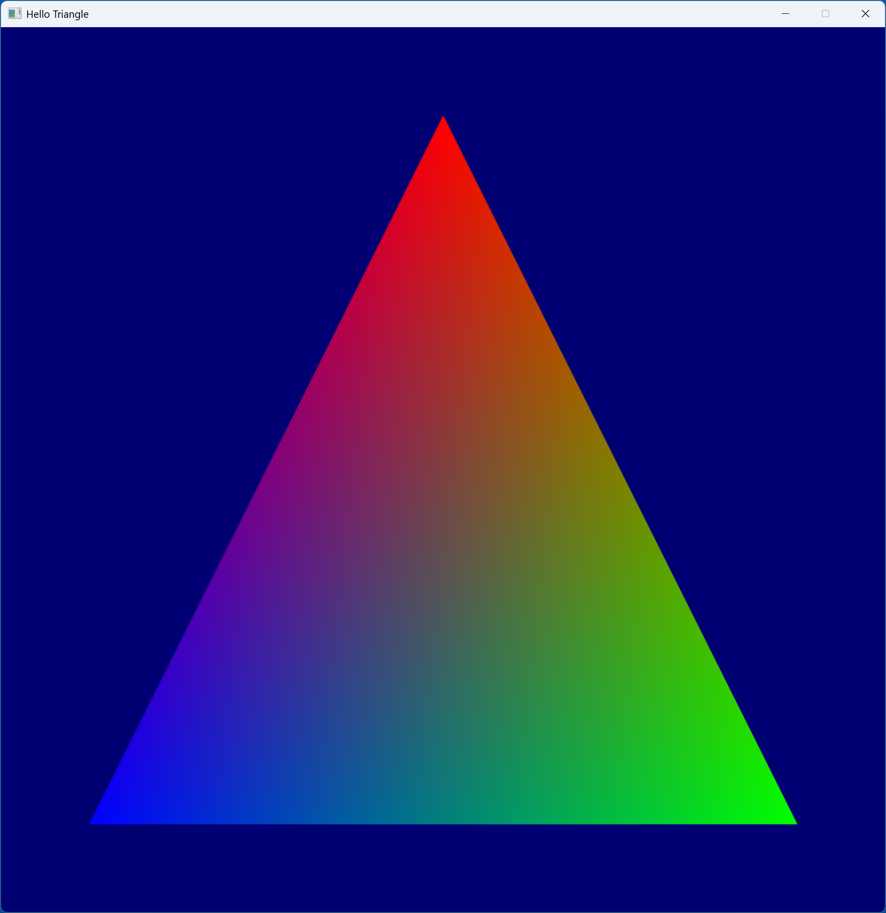
We begin by defining the actual vertices. Each vertex has 2 attributes, the position and color, both of which are 3D floating point values.
1.struct Vertex
2.{
3. float position[3];
4. float color[3];
5.};
6.static constexpr const Vertex TriangleVertices[] =
8.{
9. { // vertex 0
10. { −0.8f, +0.8f, 0.0f }, // position
11. { 0.0f, 0.0f, 1.0f } // color
12. },
13. { // vertex 1
14. { +0.8f, +0.8f, 0.0f }, // position
15. { 0.0f, 1.0f, 0.0f } // color
16. },
17. { // vertex 2
18. { 0.0f, −0.8f, 0.0f }, // position
19. { 1.0f, 0.0f, 0.0f } // color
20. }
21.};
The next step is to create the buffer, allocate the memory, and bind the memory to that new buffer. Vulkan requires the buffer creation and memory allocation to be seperate because
it gives the programmer flexibility for memory management. For example, if we want, we can create a single memory allocation and sub-allocate that amoungst different buffers. Note that we
are using the AllocateMemory helper function we created in section 6 to allocate the memory in our primary heap.
1.VkBuffer VertexBuffer { nullptr };
2.VkDeviceMemory VertexBufferMemory { nullptr };
3....
5.VkBufferCreateInfo BufferInfo =
7.{
8. .sType = VK_STRUCTURE_TYPE_BUFFER_CREATE_INFO,
9. .pNext = nullptr,
10. .flags = 0,
11. .size = sizeof(TriangleVertices),
12. .usage = VK_BUFFER_USAGE_VERTEX_BUFFER_BIT | VK_BUFFER_USAGE_TRANSFER_DST_BIT,
13. .sharingMode = VK_SHARING_MODE_EXCLUSIVE,
14. .queueFamilyIndexCount = 0,
15. .pQueueFamilyIndices = nullptr
16.};
17.Assert(vkCreateBuffer(Device, &BufferInfo, nullptr, &VertexBuffer) == VK_SUCCESS, "Failed to create vertex buffer");
19.VkMemoryRequirements VertexBufferRequirements = {};
21.AllocateMemory(VertexBuffer, PrimaryHeap, VertexBufferRequirements, VertexBufferMemory);
22.Assert(vkBindBufferMemory(Device, VertexBuffer, VertexBufferMemory, 0) == VK_SUCCESS, "Failed to bind vertex buffer memory");
After the vertex buffer has been prepared, we can copy the vertex data into the upload buffer we created in section 6. Here we also tell Vulkan to flush the memory to make sure all the writes have gone through before moving onto the next steps where we will transfer the data to the primary allocation.
After the vertex buffer is allocated in the primary heap, we have to populate it with the vertex data. Recall from section 6 on the memory heaps, we have 2 cases here:
- All the VRAM is CPU visible, so we can copy our vertex data directly to the primary heap
- Only a small segment of the VRAM is CPU visible, so we must use an upload buffer in the System RAM and then use a copy command to transfer the vertex data to the primary heap
If it is the second case, we have to do the following steps:
- Copy the vertex data to the upload heap
- Flush the memory to make sure the all the vertex data has been finished being written
- Generate the copy command buffer to copy the contents from the upload heap to the primary heap allocation
- Submit the copy command buffer
- Wait for the copy command buffer to finish the transfer
1.if (UploadBufferCpuVA)
2.{
3. // If the upload heap is being used, we have to copy our allocation to the upload buffer, and then transfer it to the primary allocation
4. VkMappedMemoryRange FlushRange =
5. {
6. .sType = VK_STRUCTURE_TYPE_MAPPED_MEMORY_RANGE,
7. .pNext = nullptr,
8. .memory = UploadBufferMemory,
9. .offset = 0,
10. .size = VK_WHOLE_SIZE
11. };
12. memcpy(reinterpret_cast<uint8_t*>(UploadBufferCpuVA), TriangleVertices, sizeof(TriangleVertices));
14. Assert(vkFlushMappedMemoryRanges(Device, 1, &FlushRange) == VK_SUCCESS, "Failed to flush vertex buffer memory");
15. // Generate the command buffer to copy the vertex data from the upload buffer to the vertex buffer
17. VkCommandBufferBeginInfo CommandBufferBeginInfo =
18. {
19. .sType = VK_STRUCTURE_TYPE_COMMAND_BUFFER_BEGIN_INFO,
20. .pNext = nullptr,
21. .flags = VK_COMMAND_BUFFER_USAGE_ONE_TIME_SUBMIT_BIT,
22. .pInheritanceInfo = nullptr
23. };
24. VkBufferCopy CopyCmd =
26. {
27. .srcOffset = 0,
28. .dstOffset = 0,
29. .size = sizeof(TriangleVertices)
30. };
31. Assert(vkBeginCommandBuffer(CommandBuffer, &CommandBufferBeginInfo) == VK_SUCCESS, "Failed to initialize command buffer");
33. vkCmdCopyBuffer(CommandBuffer, UploadBuffer, VertexBuffer, 1, &CopyCmd);
34. Assert(vkEndCommandBuffer(CommandBuffer) == VK_SUCCESS, "Failed to finalize command buffer");
35. // Submit the copy command buffer to the graphics queue and wait for the copy to finish
37. VkSubmitInfo SubmitInfo =
38. {
39. .sType = VK_STRUCTURE_TYPE_SUBMIT_INFO,
40. .pNext = nullptr,
41. .waitSemaphoreCount = 0,
42. .pWaitSemaphores = nullptr,
43. .pWaitDstStageMask = nullptr,
44. .commandBufferCount = 1,
45. .pCommandBuffers = &CommandBuffer,
46. .signalSemaphoreCount = 0,
47. .pSignalSemaphores = nullptr
48. };
49. Assert(vkQueueSubmit(GraphicsQueue, 1, &SubmitInfo, Fence) == VK_SUCCESS, "Failed to submit command buffer");
51. Assert(vkWaitForFences(Device, 1, &Fence, VK_TRUE, 1 * NANOSECONDS_PER_SECOND) == VK_SUCCESS, "Fence timeout");
52. Assert(vkResetFences(Device, 1, &Fence) == VK_SUCCESS, "Could not reset fence");
53.}
If it is the first case, then it is very simple. We simply write the vertex data directly into the primary heap.
54.else
55.{
56. // If we don't need an upload heap, it means we can map the primary buffer's memory and copy our vertex data directly to it
57. void* VertexBufferCpuVA = nullptr;
58. Assert(vkMapMemory(Device, VertexBufferMemory, 0, VertexBufferRequirements.size, 0, &VertexBufferCpuVA) == VK_SUCCESS, "Failed to map vertex buffer memory");
59. VkMappedMemoryRange FlushRange =
61. {
62. .sType = VK_STRUCTURE_TYPE_MAPPED_MEMORY_RANGE,
63. .pNext = nullptr,
64. .memory = VertexBufferMemory,
65. .offset = 0,
66. .size = VK_WHOLE_SIZE
67. };
68. // Copy the vertex data to the CPU mapped memory
70. memcpy(reinterpret_cast<uint8_t*>(VertexBufferCpuVA), TriangleVertices, sizeof(TriangleVertices));
71. Assert(vkFlushMappedMemoryRanges(Device, 1, &FlushRange) == VK_SUCCESS, "Failed to flush vertex buffer memory");
72. // Unmap the vertex buffer - we don't need it to be CPU accessible anymore
74. vkUnmapMemory(Device, VertexBufferMemory);
75.}
The next step is to create the vertex and fragment shaders for rendering our triangle.
The vertex shader will be run once per vertex of our triangle. We will take in the vertex position from the vertex buffer in index 0, and the color in index 1. Remember these indices, they will be important for the next section where
we will create the graphics pipeline. The vertex's position will to be written to gl_Position, which tells Vulkan the coordinate of the vertex, and the color will be sent to
the fragment shader at index 0.
1.#version 450
2.layout(location = 0) in vec3 VertexPosition;
4.layout(location = 1) in vec3 VertexColor;
5.layout(location = 0) out vec3 ColorOut;
7.void main()
9.{
10. gl_Position = vec4(VertexPosition, 1.0);
11. ColorOut = VertexColor;
13.}
The fragment shader will also be simple - it will simply output the color it receives from the vertex shader. Vulkan will automatically interpolate the colors between the vertices.
1.#version 450
2.layout(location = 0) in vec3 ColorIn;
4.layout(location = 0) out vec4 FragColor;
6.void main()
8.{
9. FragColor = vec4(ColorIn, 1.0);
10.}
After the shaders are implemented, we have to compile them into an intermediate representation for Vulkan. This can be done using the glslangvalidator
compiler. There are two options - we can either output a binary file which we can read/load at runtime, or we can produce header files which we can simply include
into our source code and bake the intermediate code into our application. We will be going with the second approach.
                                glslangvalidator -V --vn VertexShader -S vert VertexShader.vert.glsl -o VertexShader.vert.h
                                glslangvalidator -V --vn FragmentShader -S frag FragmentShader.frag.glsl -o FragmentShader.frag.h
Flag descriptions:
-V: tells the compiler to generate SPIR-V code--vn: tells the compiler what we want to output a header file, and what to name the array variable-S: tells the compiler the type of shader this is (vertfor the vertex shader andfragfor the fragment shader)-o: tells the compiler the generated header file's name
Once the intermediate representation headers are generated, we can include those headers and create VkShaderModule objects for each shader. This will be required for the
graphics pipeline in the next section.
1.#include "VertexShader.vert.h"
2.#include "FragmentShader.frag.h"
3....
5.VkShaderModuleCreateInfo VertexShaderInfo =
7.{
8. .sType = VK_STRUCTURE_TYPE_SHADER_MODULE_CREATE_INFO,
9. .pNext = nullptr,
10. .flags = 0,
11. .codeSize = sizeof(VertexShader),
12. .pCode = VertexShader
13.};
14.VkShaderModuleCreateInfo FragmentShaderInfo =
16.{
17. .sType = VK_STRUCTURE_TYPE_SHADER_MODULE_CREATE_INFO,
18. .pNext = nullptr,
19. .flags = 0,
20. .codeSize = sizeof(FragmentShader),
21. .pCode = FragmentShader
22.};
23.VkShaderModule VertexShaderModule = nullptr;
25.VkShaderModule FragmentShaderModule = nullptr;
26.Assert(vkCreateShaderModule(Device, &VertexShaderInfo, nullptr, &VertexShaderModule) == VK_SUCCESS, "Could not create vertex shader module");
28.Assert(vkCreateShaderModule(Device, &FragmentShaderInfo, nullptr, &FragmentShaderModule) == VK_SUCCESS, "Could not create fragment shader module");
Once we have the shaders ready, we have to create the graphics pipeline. The graphics pipeline is a very important object which controls many rendering options/parameters and contains the shaders that will be used for rendering. Before creating the graphics pipeline, we have to create a pipeline layout and also configure several required structures.
The VkPipelineLayout tells Vulkan the descriptor sets and push constants which will be able to this graphics pipeline. In this example,
we don't have any of those, so we simply create the layout.
1.VkPipelineLayout PipelineLayout { nullptr };
2....
4.VkPipelineLayoutCreateInfo PipelineLayoutInfo =
6.{
7. .sType = VK_STRUCTURE_TYPE_PIPELINE_LAYOUT_CREATE_INFO,
8. .pNext = nullptr,
9. .flags = 0,
10. .setLayoutCount = 0,
11. .pSetLayouts = nullptr,
12. .pushConstantRangeCount = 0,
13. .pPushConstantRanges = nullptr
14.};
15.Assert(vkCreatePipelineLayout(Device, &PipelineLayoutInfo, nullptr, &PipelineLayout) == VK_SUCCESS, "Failed to create pipeline layout");
The first structure we have to configure is VkPipelineShaderStageCreateInfo. This structure will tell Vulkan the shaders this pipeline will use for rendering. We have to fill out two of these,
one for the vertex shader and one for the fragment shader. The graphics pipeline creation structure will take in an array of this structure, so we define it as an array of size two.
The shader modules we created in the previous section will be used in the module field; and the pName field tells Vulkan the entry point/function
of the shader, which is main in both of our shader implementations.
                                 1.VkPipelineShaderStageCreateInfo PipelineShaderStageInfo[2] =
                                 2.{
                                 3.    {
                                 4.        .sType = VK_STRUCTURE_TYPE_PIPELINE_SHADER_STAGE_CREATE_INFO,
                                 5.        .pNext = nullptr,
                                 6.        .flags = 0,
                                 7.        .stage = VK_SHADER_STAGE_VERTEX_BIT,
                                 8.        .module = VertexShaderModule,
                                 9.        .pName = "main",
                                10.        .pSpecializationInfo = nullptr
                                11.    },
                                12.    {
                                13.        .sType = VK_STRUCTURE_TYPE_PIPELINE_SHADER_STAGE_CREATE_INFO,
                                14.        .pNext = nullptr,
                                15.        .flags = 0,
                                16.        .stage = VK_SHADER_STAGE_FRAGMENT_BIT,
                                17.        .module = FragmentShaderModule,
                                18.        .pName = "main",
                                19.        .pSpecializationInfo = nullptr
                                20.    }
                                21.};
Next is the VkPipelineVertexInputStateCreateInfo structure, which describes the vertex buffers and data format to Vulkan. This structure takes in an array of two other structures -
VkVertexInputBindingDescription and VkVertexInputAttributeDescription.
The VkVertexInputBindingDescription structure describes each vertex buffer which will be bound to this pipeline for rendering. We have all our data
in one buffer, so we only create one. The stride tells Vulkan how far apart each vertex's data is; in our case its the size of a vertex. The inputRate specifies whether
the vertex data is per vertex or per instance. The other structure, VkVertexInputAttributeDescription, will be used to describe each vertex attribute this pipeline will work with.
The location field tells Vulkan the index of the attribute, recall the vertex shader indices from the previous section. The binding field specifies
which vertex buffer, from the VkVertexInputBindingDescription array, it will get this attribute from. The format just tells Vulkan the format of this attribute,
i.e. the number of components, the number of bits per component, etc. Lastly the offset is used to determine the offset at which the first attribute is located in the buffer.
1.VkVertexInputBindingDescription Bindings[] =
2.{
3. {
4. .binding = 0,
5. .stride = sizeof(Vertex),
6. .inputRate = VK_VERTEX_INPUT_RATE_VERTEX
7. }
8.};
9.VkVertexInputAttributeDescription Attributes[] =
11.{
12. {
13. .location = 0,
14. .binding = 0,
15. .format = VK_FORMAT_R32G32B32_SFLOAT,
16. .offset = offsetof(Vertex, position)
17. },
18. {
19. .location = 1,
20. .binding = 0,
21. .format = VK_FORMAT_R32G32B32_SFLOAT,
22. .offset = offsetof(Vertex, color)
23. }
24.};
25.VkPipelineVertexInputStateCreateInfo PipelineVertexInputStateInfo =
27.{
28. .sType = VK_STRUCTURE_TYPE_PIPELINE_VERTEX_INPUT_STATE_CREATE_INFO,
29. .pNext = nullptr,
30. .flags = 0,
31. .vertexBindingDescriptionCount = sizeof(Bindings) / sizeof(VkVertexInputBindingDescription),
32. .pVertexBindingDescriptions = Bindings,
33. .vertexAttributeDescriptionCount = sizeof(Attributes) / sizeof(VkVertexInputAttributeDescription),
34. .pVertexAttributeDescriptions = Attributes
35.};
The next required structure is VkPipelineInputAssemblyStateCreateInfo, which tells the Vulkan how to assemble the
primitives for rendering. We want our vertex data to be assembled into triangles, so we use VK_PRIMITIVE_TOPOLOGY_TRIANGLE_LIST.
                                1.VkPipelineInputAssemblyStateCreateInfo PipelineInputAssemblyStateInfo =
                                2.{
                                3.    .sType = VK_STRUCTURE_TYPE_PIPELINE_INPUT_ASSEMBLY_STATE_CREATE_INFO,
                                4.    .pNext = nullptr,
                                5.    .flags = 0,
                                6.    .topology = VK_PRIMITIVE_TOPOLOGY_TRIANGLE_LIST,
                                7.    .primitiveRestartEnable = VK_FALSE
                                8.};
Next is the VkPipelineViewportStateCreateInfo structure which tells Vulkan the rendering viewport and the scissor test rectangle.
Vulkan will render into the area given by the viewport rectangle, and discard pixels outside of the scissor test rectangle. For this program Vulkan can render to the entire screen, so we construct both the viewport and scissor test rectangle
to cover the entire screen.
1.VkViewport Viewport =
2.{
3. .x = 0.0f,
4. .y = 0.0f,
5. .width = static_cast<float>(WIDTH),
6. .height = static_cast<float>(HEIGHT),
7. .minDepth = 0.0f,
8. .maxDepth = 1.0f
9.};
10.VkRect2D Scissor =
12.{
13. .offset =
14. {
15. .x = 0,
16. .y = 0
17. },
18. .extent =
19. {
20. .width = WIDTH,
21. .height = HEIGHT
22. }
23.};
24.VkPipelineViewportStateCreateInfo PipelineViewportStateInfo =
26.{
27. .sType = VK_STRUCTURE_TYPE_PIPELINE_VIEWPORT_STATE_CREATE_INFO,
28. .pNext = nullptr,
29. .flags = 0,
30. .viewportCount = 1,
31. .pViewports = &Viewport,
32. .scissorCount = 1,
33. .pScissors = &Scissor
34.};
Next is the VkPipelineRasterizationStateCreateInfo structure which controls rasterization options. We are interested in
polygonMode, cullMode, and frontFace. The polygonMode field controls how the rasterizer will render
polygons, in our case we want it to fill them in so we use VK_POLYGON_MODE_FILL. The frontFace field tells the rasterizer
which triangles are considered facing "front". We use VK_FRONT_FACE_COUNTER_CLOCKWISE, which means that triangles with their vertices ordered in
a counter clockwise order will be considered to be facing the front. This is important because we can use an important optimization called
back face culling, which will skip rendering triangles facing away from the viewer. Back face culling can be enabled by setting the cullMode
to VK_CULL_MODE_BACK_BIT. This won't affect this program since our triangle always faces in front, but eventually when we start rendering 3D models/scenes
it will matter. The rest of the options will be left to the defaults/zero.
                                 1.VkPipelineRasterizationStateCreateInfo PipelineRasterizationStateInfo =
                                 2.{
                                 3.    .sType = VK_STRUCTURE_TYPE_PIPELINE_RASTERIZATION_STATE_CREATE_INFO,
                                 4.    .pNext = nullptr,
                                 5.    .flags = 0,
                                 6.    .depthClampEnable = VK_FALSE,
                                 7.    .rasterizerDiscardEnable = VK_FALSE,
                                 8.    .polygonMode = VK_POLYGON_MODE_FILL,
                                 9.    .cullMode = VK_CULL_MODE_BACK_BIT,
                                10.    .frontFace = VK_FRONT_FACE_COUNTER_CLOCKWISE,
                                11.    .depthBiasEnable = VK_FALSE,
                                12.    .depthBiasConstantFactor = 0.0f,
                                13.    .depthBiasClamp = 0.0f,
                                14.    .depthBiasSlopeFactor = 0.0f,
                                15.    .lineWidth = 1.0f
                                16.};
Next is the VkPipelineMultisampleStateCreateInfo structure. This structure controls the multisampling options. In this program
we do not need to change anything, we just leave it with the defaults.
                                 1.VkPipelineMultisampleStateCreateInfo PipelineMultisampleStateInfo =
                                 2.{
                                 3.    .sType = VK_STRUCTURE_TYPE_PIPELINE_MULTISAMPLE_STATE_CREATE_INFO,
                                 4.    .pNext = nullptr,
                                 5.    .flags = 0,
                                 6.    .rasterizationSamples = VK_SAMPLE_COUNT_1_BIT,
                                 7.    .sampleShadingEnable = VK_FALSE,
                                 8.    .minSampleShading = 0.0f,
                                 9.    .pSampleMask = nullptr,
                                10.    .alphaToCoverageEnable = VK_FALSE,
                                11.    .alphaToOneEnable = VK_FALSE
                                12.};
The next structure is VkPipelineColorBlendStateCreateInfo which controls the color blending options. This structure requires an array of VkPipelineColorBlendAttachmentState structures,
and the length of the array should match the number of color attachments which this pipeline will render to. In our case we are only rendering to one attachment, so our array will be of size one.
We are not using any blending in this program, so we will leave everything default, except for the colorWriteMask field of the VkPipelineColorBlendAttachmentState structure, because
that controls the components that can be written to the color attachment.
1.VkPipelineColorBlendAttachmentState PipelineColorBlendAttachmentState =
2.{
3. .blendEnable = VK_FALSE,
4. .srcColorBlendFactor = VK_BLEND_FACTOR_ZERO,
5. .dstColorBlendFactor = VK_BLEND_FACTOR_ZERO,
6. .colorBlendOp = VK_BLEND_OP_ADD,
7. .srcAlphaBlendFactor = VK_BLEND_FACTOR_ZERO,
8. .dstAlphaBlendFactor = VK_BLEND_FACTOR_ZERO,
9. .alphaBlendOp = VK_BLEND_OP_ADD,
10. .colorWriteMask = VK_COLOR_COMPONENT_R_BIT | VK_COLOR_COMPONENT_G_BIT | VK_COLOR_COMPONENT_B_BIT | VK_COLOR_COMPONENT_A_BIT
11.};
12.VkPipelineColorBlendStateCreateInfo PipelineColorBlendStateInfo =
14.{
15. .sType = VK_STRUCTURE_TYPE_PIPELINE_COLOR_BLEND_STATE_CREATE_INFO,
16. .pNext = nullptr,
17. .flags = 0,
18. .logicOpEnable = VK_FALSE,
19. .logicOp = VK_LOGIC_OP_CLEAR,
20. .attachmentCount = 1,
21. .pAttachments = &PipelineColorBlendAttachmentState,
22. .blendConstants = { 0.0f, 0.0f, 0.0f, 0.0f }
23.};
The next structure is VkPipelineDepthStencilStateCreateInfo, which controls the depth and stencil test options. We are not using the depth or stencil test in this program,
so we leave all the parameters as default.
                                 1.VkPipelineDepthStencilStateCreateInfo DepthStencilInfo =
                                 2.{
                                 3.    .sType = VK_STRUCTURE_TYPE_PIPELINE_DEPTH_STENCIL_STATE_CREATE_INFO,
                                 4.    .pNext = nullptr,
                                 5.    .flags = 0,
                                 6.    .depthTestEnable = VK_FALSE,
                                 7.    .depthWriteEnable = VK_FALSE,
                                 8.    .depthCompareOp = VK_COMPARE_OP_NEVER,
                                 9.    .depthBoundsTestEnable = VK_FALSE,
                                10.    .stencilTestEnable = VK_FALSE,
                                11.    .front =
                                12.    {
                                13.        .failOp = VK_STENCIL_OP_KEEP,
                                14.        .passOp = VK_STENCIL_OP_KEEP,
                                15.        .depthFailOp = VK_STENCIL_OP_KEEP,
                                16.        .compareOp = VK_COMPARE_OP_NEVER,
                                17.        .compareMask = 0,
                                18.        .writeMask = 0,
                                19.        .reference = 0
                                20.    },
                                21.    .back =
                                22.    {
                                23.        .failOp = VK_STENCIL_OP_KEEP,
                                24.        .passOp = VK_STENCIL_OP_KEEP,
                                25.        .depthFailOp = VK_STENCIL_OP_KEEP,
                                26.        .compareOp = VK_COMPARE_OP_NEVER,
                                27.        .compareMask = 0,
                                28.        .writeMask = 0,
                                29.        .reference = 0
                                30.    },
                                31.    .minDepthBounds = 0.0f,
                                32.    .maxDepthBounds = 0.0f
                                33.};
Once we have all these structures prepared, we can create the graphics pipeline.
1.VkPipeline GraphicsPipeline { nullptr };
2....
4.VkGraphicsPipelineCreateInfo GraphicsPipelineInfo =
6.{
7. .sType = VK_STRUCTURE_TYPE_GRAPHICS_PIPELINE_CREATE_INFO,
8. .pNext = nullptr,
9. .flags = 0,
10. .stageCount = 2,
11. .pStages = PipelineShaderStageInfo,
12. .pVertexInputState = &PipelineVertexInputStateInfo,
13. .pInputAssemblyState = &PipelineInputAssemblyStateInfo,
14. .pTessellationState = nullptr,
15. .pViewportState = &PipelineViewportStateInfo,
16. .pRasterizationState = &PipelineRasterizationStateInfo,
17. .pMultisampleState = &PipelineMultisampleStateInfo,
18. .pDepthStencilState = &DepthStencilInfo,
19. .pColorBlendState = &PipelineColorBlendStateInfo,
20. .pDynamicState = nullptr,
21. .layout = PipelineLayout,
22. .renderPass = RenderPass,
23. .subpass = 0,
24. .basePipelineHandle = nullptr,
25. .basePipelineIndex = −1
26.};
27.Assert(vkCreateGraphicsPipelines(Device, nullptr, 1, &GraphicsPipelineInfo, nullptr, &GraphicsPipeline) == VK_SUCCESS, "Failed to create graphics pipeline");
Once the graphics pipeline is created, we can free the shader modules.
1.if (VertexShaderModule != nullptr)
2.{
3. vkDestroyShaderModule(Device, VertexShaderModule, nullptr);
4. VertexShaderModule = nullptr;
5.}
6.if (FragmentShaderModule != nullptr)
8.{
9. vkDestroyShaderModule(Device, FragmentShaderModule, nullptr);
10. FragmentShaderModule = nullptr;
11.}
Once we have the vertex buffer and graphics pipeline set up, we can implement the actual rendering logic! The main loop will call this code every frame to render the triangle, until the user closes the program.
The first step is to get the next swapchain image using vkAcquireNextImageKHR. This will give us the index of the next available image. We use the RenderSemaphore
from section 7 here. When the image is available/ready to be rendered to, this semaphore will be signalled. When we submit the work to the graphics queue, the graphics queue will wait for
this semaphore to become signalled before beginning rendering.
1.uint32_t FrameIndex { 0 }; // 0 to NumSwapchainImages
2....
4.uint32_t SwapchainIndex = 0;
6.Assert(vkAcquireNextImageKHR(Device, Swapchain, 1 * NANOSECONDS_PER_SECOND, RenderSemaphores[FrameIndex], nullptr, &SwapchainIndex) == VK_SUCCESS, "Could not get next surface image");
After we know which framebuffer/swapchain image we will be rendering to, we begin preparing the command buffer which will contain all our rendering commands.
1.VkCommandBufferBeginInfo CommandBufferBeginInfo =
2.{
3. .sType = VK_STRUCTURE_TYPE_COMMAND_BUFFER_BEGIN_INFO,
4. .pNext = nullptr,
5. .flags = VK_COMMAND_BUFFER_USAGE_ONE_TIME_SUBMIT_BIT,
6. .pInheritanceInfo = nullptr
7.};
8.Assert(vkBeginCommandBuffer(CommandBuffer, &CommandBufferBeginInfo) == VK_SUCCESS, "Failed to initialize command buffer");
The first command we insert into the command buffer is to set up the render pass. This will prepare the framebuffer which we are rendering to. Here we use the render pass object we created earlier and the current framebuffer, and we also specify the rendering area (the whole screen) and the clear color (blue in this case).
1.// Color buffer clear color
2.VkClearValue ClearColor;
3.ClearColor.color.float32[0] = 0.00f;
4.ClearColor.color.float32[1] = 0.00f;
5.ClearColor.color.float32[2] = 0.45f;
6.ClearColor.color.float32[3] = 0.00f;
7.VkRect2D RenderArea =
9.{
10. .offset =
11. {
12. .x = 0,
13. .y = 0
14. },
15. .extent =
16. {
17. .width = WIDTH,
18. .height = HEIGHT
19. }
20.};
21.VkRenderPassBeginInfo RenderPassBeginInfo =
23.{
24. .sType = VK_STRUCTURE_TYPE_RENDER_PASS_BEGIN_INFO,
25. .pNext = nullptr,
26. .renderPass = RenderPass,
27. .framebuffer = Framebuffers[SwapchainIndex],
28. .renderArea = RenderArea,
29. .clearValueCount = 1,
30. .pClearValues = &ClearColor
31.};
32.vkCmdBeginRenderPass(CommandBuffer, &RenderPassBeginInfo, VK_SUBPASS_CONTENTS_INLINE);
After the framebuffer is prepared, we bind our graphics pipeline.
1.vkCmdBindPipeline(CommandBuffer, VK_PIPELINE_BIND_POINT_GRAPHICS, GraphicsPipeline);
Next we bind the vertex buffer, and tell Vulkan to render the triangle.
1.uint64_t pOffsets[1] = { 0 };
2.VkBuffer pBuffers[1] = { VertexBuffer };
3.const uint32_t VertexCount = sizeof(TriangleVertices) / sizeof(Vertex);
4.vkCmdBindVertexBuffers(CommandBuffer, 0, 1, pBuffers, pOffsets);
6.vkCmdDraw(CommandBuffer, VertexCount, 1, 0, 0);
After we are done with our rendering commands, we can end the render pass, and finalize the command buffer.
1.vkCmdEndRenderPass(CommandBuffer);
2.Assert(vkEndCommandBuffer(CommandBuffer) == VK_SUCCESS, "Failed to finalize command buffer");
Once the command buffer is populated, we have to submit it to our graphics queue. The VkSubmitInfo structure will specify the command buffer we are submitting, and it
will also specify the semaphores which the queue should wait on before beginning rendering. As mentioned before, we want the graphics queue to wait for the framebuffer to become
available before it starts rendering, so we use our RenderSemaphore from earlier here. We want the graphics queue to wait at the top of the pipe, meaning before any of the shader stages begin, so we use VK_PIPELINE_STAGE_TOP_OF_PIPE_BIT
as the waiting stage. Note that we also give another semaphore, PresentSemaphore , to be signalled once the command buffer is finished executing/rendering - this will be required to know when the image can be presented.
1.VkPipelineStageFlags WaitDstStageMasks[] = { VK_PIPELINE_STAGE_TOP_OF_PIPE_BIT };
2.VkSubmitInfo SubmissionInfo =
4.{
5. .sType = VK_STRUCTURE_TYPE_SUBMIT_INFO,
6. .pNext = nullptr,
7. .waitSemaphoreCount = 1,
8. .pWaitSemaphores = &RenderSemaphores[FrameIndex],
9. .pWaitDstStageMask = WaitDstStageMasks,
10. .commandBufferCount = 1,
11. .pCommandBuffers = &CommandBuffer,
12. .signalSemaphoreCount = 1,
13. .pSignalSemaphores = &PresentSemaphores[FrameIndex]
14.};
15.Assert(vkQueueSubmit(GraphicsQueue, 1, &SubmissionInfo, Fence) == VK_SUCCESS, "Failed to submit command buffer");
At this point, the command buffer has been submitted to the queue, and we can ask Vulkan to present the new image when its available. The PresentSemaphore will be signalled
once the rendering operations finish and the next image is ready to be presented. We will out the structure VkPresentInfoKHR with the swapchain, current swapchain index, and the PresentSemaphore, and
call vkQueuePresentKHR.
1.VkPresentInfoKHR PresentInfo =
2.{
3. .sType = VK_STRUCTURE_TYPE_PRESENT_INFO_KHR,
4. .pNext = nullptr,
5. .waitSemaphoreCount = 1,
6. .pWaitSemaphores = &PresentSemaphores[FrameIndex],
7. .swapchainCount = 1,
8. .pSwapchains = &Swapchain,
9. .pImageIndices = &SwapchainIndex,
10. .pResults = nullptr
11.};
12.Assert(vkQueuePresentKHR(GraphicsQueue, &PresentInfo) == VK_SUCCESS, "Failed to present");
The semaphores we used above will insert the waits into the command queue and syncronize the GPU commands, but we also need to make sure the CPU is syncronized.
We will accomplish this by waiting on the vkQueueSubmit fence. Once this fence comes back, it will mean that the previous rendering operation is finished and we can
begin preparing the next frame. Note that this does not mean presentation has also finished, but that is ok because the next frame will be rendered to the next swapchain image.
Even if we fill all the available swapchain images, eventually the queue will have to wait for the next swapchain image to become available, and the wait on the fence will block the CPU.
1.Assert(vkWaitForFences(Device, 1, &Fence, VK_TRUE, 1 * NANOSECONDS_PER_SECOND) == VK_SUCCESS, "Fence timeout");
2.Assert(vkResetFences(Device, 1, &Fence) == VK_SUCCESS, "Could not reset fence");
3.FrameIndex = (FrameIndex + 1) % NumSwapchainImages;
In other words, fences are used to syncronize the CPU and GPU, and semaphores are used to syncronize GPU commands. Note that waiting on this fence after every submission is not optimal. In an actual application, you would start preparing the next frame while the GPU works on the current one. This is Vulkan's biggest advantage, it allows the CPU and GPU to work in parallel and minimize bottlenecking/idling. However, to keep this tutorial as simple as possible, we wait after every submission.
Lastly, we add our infinite loop to render and then update, until the user closes our application.
                                1.void Run(void)
                                2.{
                                3.    while (Running)
                                4.    {
                                5.        Update();
                                6.        Render();
                                7.    }
                                8.}
Once you have made it here, we can finally see our precious triangle :) !
When the application is closed, we have to free all our allocations/objects otherwise we will leak the memory. For that please see the destructor
~HelloTriangle in the source code.